Blog Categories
Recent Posts
The Structure And Working Principle Of Our Company's Precession Vortex Flowmeter Are Introduced
Ⅰ.General
LUXQ series intelligent precession vortex flowmeter is a new type of gas flowmeter developed by our company with domestic leading level. The flowmeter integrates flow, temperature and pressure detection functions, and can automatically compensate for temperature, pressure and compression factors.
LUXQ series intelligent precession vortex flowmeter can be widely used in industries such as petroleum, chemical, electric power, metallurgy, urban gas supply to measure various gas flows, which is the first choice for oil and gas transmission and metering and trade measurement.
Ⅱ.Structure and working principle
Flowmeter Structure
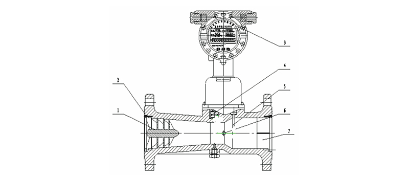
The flow meter consists of the following seven basic components (fig.1) :
1.Vortex generator
It is made of aluminum alloy and has an angled spiral blade that is fixed at the front of the contraction section of the housing to force the fluid to produce a strong vortex flow.
2.Housing
It has a flange and has a certain shape fluid passage. According to different working pressures, the housing material can be cast aluminum alloy or stainless steel.
3.Intelligent flowmeter totalizer
It consists of temperature, pressure detection analog channel, flow detection digital channel and micro-processing unit, liquid crystal drive circuit and other auxiliary circuits, and is equipped with external output signal interface. The flow totalizer consists of temperature and pressure detection analog channel, flow sensing channel, and micro-processing unit and is equipped with external output signal interface to output various signals, and the microprocessor in the flowmeter performs temperature and pressure compensation according to the gas equation, and perform the compression factor correction automatically, and the gas equation is as follows:
![]()
Where:
QN Volume flow under standard condition(m3/h)
QV Volume flow under working condition(m3/h)
Pa Local atmospheric pressure (KPa)
P Meter pressure measured at flowmeter pressure hole (KPa)
PN Atmospheric pressure under standard condition (101.325KPa)
TN Absolute temperature (293.15K) under standard condition
T Absolute temperature(K) of the measured fluid
ZN Compression factor of gas under standard condition
Z Compression factor of gas under working condition
Note: when using a bell jar or negative pressure for calibration, take ZNZ=1, for natural gas, (ZN/Z)1/2=FZ is the super-compression factor, and it is calculated according to the formula in the standard of SY/T6143-1996 of China National Petroleum Corporation.
4.Temperature sensor
The Pt100 platinum resistance is used as a temperature sensitive component, and its resistance value corresponds to temperature in a certain temperature range.
5.Pressure sensor
The piezoresistive diffusion silicon bridge is used as the sensitive component, and the bridge arm resistance will be expected to change under the action of external pressure. Therefore, under a certain excitation current, the potential difference between the two output terminals is proportional to the external pressure.
6.Piezoelectric sensor
It is installed near the throat of the expansion section of the housing and detects the vortex precession frequency signal.
7.Derotator
It is fixed at the outlet section of the housing and acts to eliminate vortex flow to reduce the impact on downstream meter performance.

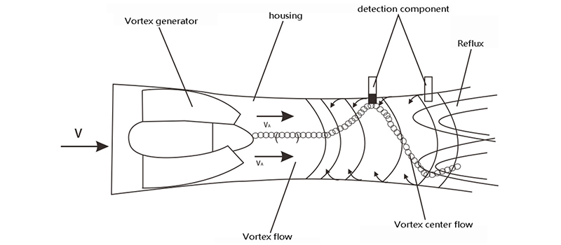
The flow sensor flow profile is similar to that of a venturi tube (Fig. 1). A set of spiral guide vanes are placed on the inlet side. When the fluid enters the flow sensor, the guide vanes forces the fluid to produce a sharp vortex flow. During the diffusion section, the vortex flow is subjected to reflux and begins to make a second rotation to form a gyro-type eddy current precession phenomenon. The precession frequency is proportional to the flow and is not affected by the physical properties and density of the fluid. The detection component measures the secondary rotation precession frequency of the fluid to obtain good linearity in a wide flow range. The signal is amplified, filtered, and shaped by a preamplifier into a pulse signal proportional to the flow rate, then,it is sent to the microprocessor for integration calculation together with the detection signals such as temperature and pressure, and finally displays the measurement results (instantaneous flow, accumulated flow and temperature, pressure data) on the LCD.


