The selection of turbine flowmeter
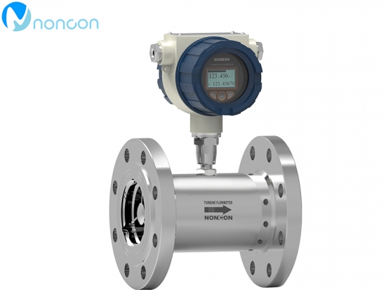
Intelligent liquid turbine flowmeter is a new intelligent instrument that integrates turbine flow sensor and display integration developed by ultra-low power consumption single chip microcomputer technology. It has the advantages of compact mechanism, intuitive and clear reading, high reliability, free from external power supply interference, lightning resistance, low cost and so on.
Installation of turbine flowmeter
The so-called intelligent turbine flowmeter refers to the part of the meter head, with field display of accumulated and instantaneous flow, 24V power supply, output current or pulse signal, the sensor is the same as the ordinary, installation requirements are the same.
Installation site of turbine flowmeter
1. The installation site shall conform to the ambient temperature within the range of -25 ~ 55℃ and the humidity < 80% RH
2, good ventilation, avoid the sun, rain
3. Avoid places with vibration or stress in piping
4. Avoid places susceptible to strong thermal radiation and radioactivity
5. The interference of strong external electromagnetic field to the detection signal must be avoided.If it cannot be avoided, measures such as shielding should be added to the amplifier of the flowmeter (sensor) to eliminate interference.
6. Flameproof amplifiers should be used in places with explosion-proof requirements
7. The installation location shall be convenient for installation, operation and maintenance
Installation posture and position of turbine flowmeter
To ensure a high measurement accuracy, the flowmeter (sensor) should be mounted horizontally on the horizontal pipe and the direction of the arrow indicating the flow direction on the flow sensor should be consistent with the flow direction of the liquid.If it must be installed vertically, the flow of the liquid should be kept upward to ensure that the body of the flow sensor is filled with liquid.
Iii. Piping requirements
1. In order to eliminate the influence of uneven distribution of cross section velocity in the pipeline on measurement accuracy, the upstream and downstream of the flow sensor should have a certain straight pipe section, or a rectifier should be installed to replace part of the straight pipe section.Generally, the upstream straight pipe segment is not less than 15D, and the downstream straight pipe segment is not less than 5D(D is the nominal diameter of the flow sensor).
2. In order to eliminate the influence of backflow, uneven flow velocity distribution and swirling flow, a rectifier can be installed upstream. At this time, the straight pipe length of the upstream part of the flow sensor L=10D, and if it is 15-20d, the measurement precision can reach the calibration precision.
3. When solid impurities are contained in the measured liquid, a filter should be installed on the upstream of the flow sensor. The mesh number of the filter is 20-60 mesh (3-9 mesh /cm2), and the mesh number of the general flow sensor with small aperture is more.The installation position of the filter should be considered to facilitate the disassembly of the filter screen.
4, the liquid mixed with gas or easy to measure the liquid gasification, should be installed air separator (gas eliminator).
5. If the tested liquid is easy to be vaporized, in order to prevent cavitation, the pressure at the outlet of the flow sensor should be higher than the calculated value Pmin below:
Pmin = 2△ P1.25 Pv: Pmin -- pressure;P -- Pressure loss of flowmeter under flow rate;Pv - Saturation vapor pressure of the measured liquid at use temperature
6, the flow through the flow sensor is too large, will make the bearing life is too short, usually through the valve to the appropriate size, the valve should be installed in the downstream of the flow meter.
7. In order not to interrupt the fluid delivery during the maintenance, the globe valve is usually installed in the upstream and downstream of the flow sensor, and the bypass pipe is set, and the bypass pipe shall not leak when the bypass valve is closed during the measurement.
8. If reverse flow is possible, add a check valve to prevent reverse flow.
9. The flow sensor shall be concentric with the pipe, and the sealing ring shall not protrude into the pipe.
10. To avoid gas accumulation within the flowmeter, the flowmeter should not be installed at the point of the horizontal line.
11. If the flowmeter is installed at the low point of the pipeline, the discharge valve should be installed in the pipeline to discharge sediment regularly.
12. The front and rear pipelines of the flow sensor should be firmly supported so that there is no obvious vibration.
13. When cleaning the newly laid pipeline, a short pipe should be connected to the part where the flow sensor is installed first, and the flow sensor should be installed after the completion of cleaning.
14. When it is necessary to measure the temperature of the fluid, it should be measured at 5 times the nominal diameter of the pipeline downstream of the flow sensor.
15. When it is necessary to measure the pressure of the fluid, it should be measured at the length of 10 times the nominal pipe diameter upstream of the flow sensor.
Related products: Flow controller instrument, Diesel oval gear flow meter


