Blog Categories
Recent Posts
How much do you know about the guided wave radar level gauge?
Measurement principle

Principle:
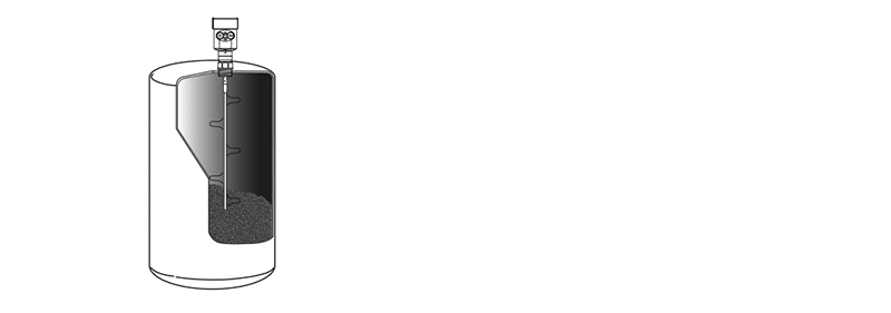
The high frequency microwave pulse emitted by the guided wave radar level gauge travels along the detection module (cable or steel bar) and encounters the measured medium. Due to the dielectric constant mutation, the reflection is caused and part of the pulse energy is reflected back.The time interval between the emitted and reflected pulses is proportional to the distance between the measured medium.
Features:
Guided wave radar level gauge can be used in a variety of complex conditions due to the advanced microprocessor and unique choDiscovery echo processing technology.
A variety of process connections and the types of detection components make the 60X series guided wave radar level gauge suitable for a variety of complex conditions and applications.Such as: high temperature, high pressure and small dielectric constant medium.
The work mode of pulse is adopted, and the radar level of guided wave is extremely low in transmitting power, which can be installed in various metal and non-metal containers, which is harmful to human body and environment.
Description:
Guided wave radar is a measuring instrument based on the principle of time travel. Radar waves move at the speed of light.The probe emits high frequency pulse and propagates along the cable or bar probe. When the pulse hits the material surface, it is reflected back to be received by the receiver in the instrument and transformed the distance signal into the level signal.
The reflected pulse signal is transmitted to the electronic circuit part of the instrument along the cable or pole probe.The correct identification of echo signal is completed by the pulse software. The distance D from the material surface is directly proportional to the time travel T of the pulse:
D=C×T/2
Where C is the speed of light
Since the distance E of the empty tank is known,
the level L is: L=E-D
Set by input of empty tank height E (= zero), full tank height F (= full range) and some application parameters, the application parameters will automatically adapt the instrument to the measuring environment,corresponding to 4-20ma output.

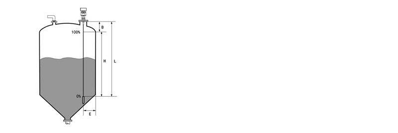
Measurement range:
Description:
H----Measurement range
L----Empty tank distance
B----Top blind area
E----Minimum distance from probe to tank wall
The blind spot on the top refers to the minimum distance between the highest material surface and the measuring reference point.
A blind spot at the bottom is a distance near the bottom of a cable that cannot be accurately measured.
There is a finite measurement distance between the top blind and the bottom blind.

Note:
Only when the material is between the blind area at the top and the blind area at the bottom, the reliable measurement of the level in the tank can be guaranteed.
Previous :
Why Sanitary Type Turbine Flow Meter?Next :
How to select a flowmeter?
