Blog Categories
Recent Posts
The working principle of turbine flowmeter and turbine transmitter is analyzed
1 Working principle of turbine transmitter
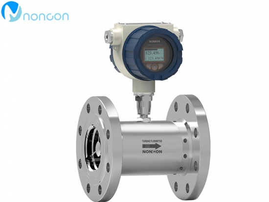
Turbine flowmeter is composed of turbine, bearing, preamplifier and display instrument.
By flow impact turbine blade body, make the turbine to rotate, the turbine speed changes along with the change of flow rate, large flow, the speed of the turbine is also big, then through magnetoelectricity conversion device of the turbine speed is converted to the corresponding frequency pulses of electricity, after preamplifier amplification into display instrument to count and, according to the number of pulses per unit time and the cumulative pulse number can be calculated instantaneous flow and cumulative flow.
The working principle of the turbine transmitter is that when the fluid flows along the axis of the pipe and impinges on the turbine blade, a force proportional to flow rate QV, flow rate V and product of fluid density ACTS on the blade and pushes the turbine to rotate.As the turbine rotates, the blades periodically cut the magnetic field lines generated by the electromagnet, changing the magnetic flux of the coils.According to the principle of electromagnetic induction, a pulsating electric potential signal is induced in the coil. The frequency of the pulsating signal is proportional to the flow rate of the measured fluid.
The pulse signal output by the turbine transmitter can be pre-amplified by the amplifier and fed into the display instrument to achieve flow measurement.
2. Selection of turbine flowmeter
(1) The main selection of the flowmeter is made of 316 stainless steel material to prevent corrosion. If the explosion area is explosion-proof, it must be the explosion proof result.
(2) Bearing generally has three specifications: tungsten carbide precision, polytetrafluoroethylene, carbon graphite, which is used as the standard industrial control parts;Teflon, carbon graphite can be anticorrosive, generally preferred in chemical sites.The square of the life velocity of the bearing is positive and negative, so the velocity of the flow at 1/3 of the velocity of the flow is better.
(3) The induction probe detects the motion of the rotating body and converts it into pulsed digital electrical signals. The output value of the electromagnetic coil voltage is close to the sinusoidal curve. The frequency range of the pulse signal varies linearly with the measured flow, and the typical range is 10:1, 25:1
And 100:1 in three sizes.Electromagnetic coil resistance of less than 2000 Ω, generally greater than this value may be damaged.
Installation of turbine flowmeter
(1) The power line of the transmitter is metal shielded wire, and the ground should be good and reliable.Power supply for dc 24 v, 650 Ω impedance.
(2) Transmitters should be installed horizontally to avoid vertical installation, and ensure that there are suitable straight pipe sections before and after the transmitter, generally 10D before and 5D after.
(3) Ensure that the flow direction of the fluid is consistent with the arrow direction of the instrument housing, and do not install backwards.
(4) The measured medium should not corrode the turbine, especially the bearing, otherwise measures should be taken.
(5) Note that the magnetic induction part should not collide.
Configuration and correction of turbine flowmeter
The standard calibration method is the ten-point water calibration method, but the values of different viscosity calibration are different, so the viscosity calibration curve is usually needed.
Display instrument of turbine flowmeter
The task of the display instrument is to convert the output pulse number per unit time and total output pulse number into instantaneous flow rate and total flow rate and display them.
By former amplifier output pulse signal, the amplitude and waveform are irregular, after entering the display instrument, first need to the shaping circuit plastic become have rules with certain amplitude of rectangular electrical pulse signal, then after transformation frequency/current circuit, the frequency signal into the corresponding current signal (4 ~ 20 ma) can convert instantaneous flow value, total amount by the transformation and integrating circuit.Some display instrument in place, some send DCS display.
6 Matters needing Attention
(1) Before installing the turbine flowmeter, the pipeline should be cleaned.When the measured medium is unclean, filter should be added.Otherwise, the turbine, bearing is easy to be stuck, the flow can not be measured.
(2) Disassembly and installation flow timing, no collision on the magnetic induction part.
(3) Setting of instrument coefficient before operation.Check carefully to make sure that the instrument connection is correct and the ground is good before sending power.
(4) When installing turbine flow timing, the front and rear pipe flanges should be horizontal, otherwise the pipe stress has a great impact on the flow meter.
Related products: sanitary electromagnetic flowmeter, electromagnetic water meter


